GIOVE-A
Center of Mass Information:
The ESA publication "Specification of Galileo and GIOVE Space Segment Properties Relevant for Satellite Laser Ranging" provides retroreflector and spacecraft information (view request cover letter). Center of mass information can be found below (provided by NERC/G. Appleby):
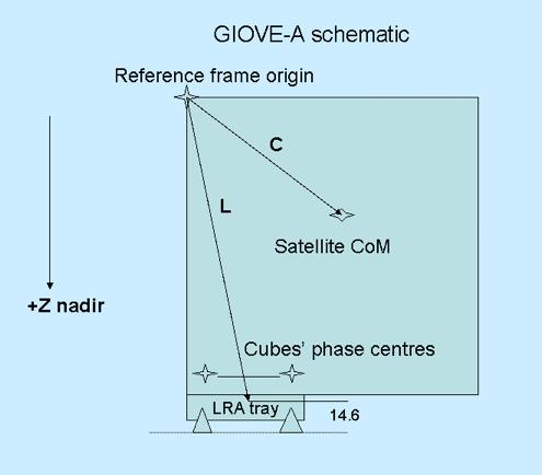
Position of the GIOVE-A laser retro phase center
Courtesy of NERC/G. Appleby
Vector C is from the spacecraft reference
point to the satellite’s centre of mass CoM.
Vector L is from the spacecraft reference point
to the mass centre of the tray containing the 76 corner cubes.
From the ESA document ‘Specification of GALILEO and GSTB-V2 Space Segment
Properties Relevant for Satellite Laser Ranging, ESTEC, Nov 2005’:
C = (-4, +1, +788) mm,
L = (-832, -654, +1489) mm
The plane of the front faces of the cubes is +14.6mm in the Z direction
from the LRA mass centre (V. Vasiliev, IPIE, Russia);
The cubes’ phase centres are -h*n in the Z direction from the plane
of the front faces of the cubes;
For the GIOVE-A cubes, h=19.1mm, n=1.46. So phase centres are
-27.9mm in Z.
So z-component of array phase centre is (-27.9 +14.6) = -13.3mm
from LRA mass centre.
So defining vector L’ as the vector from the spacecraft reference
point to the phase centre of the retro array, we have
L’ = (-832, -654, (+1489– 13)), i.e. L’ =
(-832, -654, +1476)
Finally, the vector CP from the spacecraft centre of
mass to the phase centre of the retro array is CP = L’ – C
So CP = (-832, -654, +1476) - (-4, +1, +788) = (-828,
-655, +688) in satellite fixed frame.
Attitude Law:
The GIOVE-A AOCS Normal Mode must maintain the spacecraft attitude such that the payload line of sight (nominally aligned with the spacecraft +Z Body axis) is always nadirpointing and the solar array panels (aligned with the spacecraft body Y axis) can always achieve normal solar incidence by a rotation of the solar panels around the body Y axis. To be achieved this, the spacecraft follows an attitude profile that keeps the +Z body axis nadir-pointing and the spacecraft-Sun vector nominally in the spacecraft X-Z body plane by using only a spacecraft yaw rotation throughout the orbit. In practice there are two solutions which can be used to satisfy the requirements. The selected solution maintains the +X facet of the spacecraft in a deep-space pointing attitude.
It is foreseen that the theoretical attitude will not be achieved at times where the beta angle (angle between the sun and the orbital plane) is small, due to limitations in the reactions wheels and to poor yaw measurement (sun co-linearity). In addition, during eclipse, it is expected that the yaw error can reach values of up to 18 degrees.
Other Navigation Data:
The phase centre for the navigation signal is provided here to complement the necessary information needed to perform precise orbit determination (RD-4, RD-7 and RD-8):
| E5a + E5b | E6 | E2/L1/E2 |
|---|---|---|
| X = 0.0 mm | X = 0.0 mm | X = 0.0 mm |
| Y = 0.0 mm | Y = 0.0 mm | Y = 0.0 mm |
| Z = 1690.0 mm | Z = 1665.0 mm | Z = 1658.0 mm |
The s/c mass is 582.8 Kg (valid as of March 2006). The approximate cross-section Area is 9 squared metres, with a CBSRPB (Solar Pressure Radiation factor) equals 1.37 (assuming cannonball model, according to equation 1): a=C sub(SRP) x AW/m (equation 1). A is cross-section Area, W = 4.56x10**-6xN/m**2, m is satellite mass, R sub(sun) is mean distance to Sun.