Quick Links
Space Segment
Retroreflector Array Developments
- ILRS Standard for Retroreflector Arrays at GNSS Altitudes
- Satellite/lunar laser ranging Characterization Facility (SCF) at the INFN
- Tests of a LAGEOS engineering model
- Test of a NASA hollow retroreflector prototype
- Test of a Galileo-IOV prototype retroreflector
- Test of the LLRRA-21/MoonLIGHT retroreflector
- Retroreflector Array Analysis and Modeling
- Related publications
Satellite/lunar laser ranging Characterization Facility (SCF) at the INFN
The Laboratori Nazionali di Frascati (LNF) dell’INFN has established a new test laboratory facility and test procedure to characterize and model the detailed thermal behavior and optical performance of cube corner laser retroreflectors (CCRs) for retroreflector satellites, with particular emphasis on GNSS. The tests are performed in laboratory-simulated space conditions, with a dedicated clean room of class 10000 or better are supporting programs at NASA, ESA and ASI. The laboratory is located at the INFN-LNF facility in Frascati, Italy, near Rome. The key experimental innovation is the concurrent measurement and modelling of the optical Far Field Diffraction Pattern (FFDP) and the temperature distribution of retroreflector payloads under thermal conditions produced with a close-match solar simulator. The apparatus includes infrared cameras for non-invasive thermometry, thermal control and real-time payload movement to simulate satellite orientation on orbit with respect to solar illumination and laser interrogation beams. Aside from measurements, the characterization program includes integrated thermal and optical modelling of the retroreflectors tuned to the test procedures.
These capabilities provide unique pre-launch performance validation of the space segment of LLR/SLR (Lunar/Satellite Laser Ranging) and allow for retroreflector design optimization to maximize ranging efficiency and signal-to-noise conditions in daylight. Results from tests and analyses performed on flight and prototype CCR payloads are presented in references [1][2][3][4][5] and summarized below. Between 2009 and 2010, INFN-LNF, in collaboration with international space agencies and institutions, was requested to SCF-Test, different kind of Laser Retroreflector Arrays (LRAs), whose applications span from fundamental physics to space geodesy to GNSS to R&D models. In the following we briefly describe such tests and their results.
Tests of a LAGEOS engineering model

Fig. 1. LAGEOS sector inside the SCF cryostat
The LAGEOS satellites are the standard ILRS targets for the reference frame and geodynamics studies. The LAGEOS I and II satellites are covered with 426 uncoated CCRs over a spherical surface, and were conceived to provide a long-term (many decades or even generations) stable reference in space. Uncoated CCR’s with properly insulated mounting were used to minimize thermal degradation, significantly increase optical performance, and avoid the possibility of long-term degradation due to back-coating failure. In 2009, ILFN tested an engineering model (sector) of the LAGEOS satellite provided by NASA; the model, an aluminum spherical cap of the whole satellite, is shown in Fig. 1 inside the test facility. The engineering model has a base diameter of 380 mm, a weight of 1.5 kg, and is equipped with 37 uncoated CCRs of good optical quality. The CCRs have a front face aperture of 1.5", mounted inside a cavity with the same scheme used on the Lunar Apollo arrays.
Prior to the test of the sector, all of the 37 CCRs were tested in air, with measurements of the Far Field Diffraction Pattern (FFDP) in each of the three possible orientations (physical edge vertical), to verify their adherence to the original design specifications (angles between reflecting surface of 90o+ (1.25±0.5)").
For the tests, the sector was placed inside the chamber on a rotation+tilt positioning platform with an interface copper plate. Temperature sensors recorded the temperature distribution, while the IR camera measured CCRs front face temperatures.
Measurements were performed in several conditions.
- With the Sector held at 300K we placed the polar CCR inside its housing with two different torque screws of the Aluminum retainer rings: 0.135 Nm (LAGEOS nominal value) and 0.2 Nm.
- With the screw torque of the polar CCR, as defined above, set at 0.2 Nm we maintained the Sector at three different temperatures: 280K, 300K and 320K.
Concurrent optical and thermal measurements were performed only on the polar CCR, while full thermal analysis was performed also on the first and second CCR rings of the Sector. The output of the thermal analysis was the thermal relaxation time of the CCR, τCCR, based on IR measurements of the variation of the CCRs front face temperature. These values decreased as the temperature of the Aluminum, hence of the CCR, increased, following the expression:
Fig. 2 shows instead the outcome of the optical FFDP measurements, comparing the different types of tests performed. In these plots we analyzed the variation of the intensity at 35 μrad (∼the velocity aberration of LAGEOS). An increase on the screw torque from its nominal value decreases the intensity of the FFDP in the SUN OFF phase. An increase in the temperature of the Aluminum decreases the intensity of the FFDP in the SUN OFF phase.

Fig. 2. FFDP Intensity variation during LAGEOS Sector measurements. Relative error on intensity is ±10%.
Test of a NASA hollow retroreflector prototype
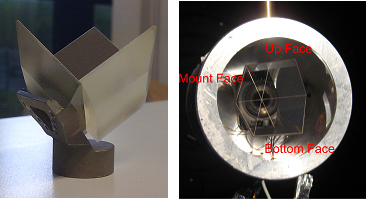
Fig. 3 The NASA-GSFC hollow retroreflector. (right) CCR in its test configuration
Hollow CCRs are being considered for several applications. A NASA prototype hollow retroreflector was tested at ILFN in 2010 [2]. This prototype was built from three Pyrex faces, with a metal reflecting surface coating of optical quality. Joints between the surfaces are made with stycast cast glue for space applications. The unit is then supported, at the bottom, by an Invar foot, screwed to one of the faces (see Fig. 3) was held inside the test facility with an Aluminum housing, with the Invar foot in thermal contact with the Aluminum. The housing was built in order to simulate the presence of other CCRs, around the sample under test, in a hypothetical array. The CCR was positioned with one physical edge, the one opposite to the face linked with the Invar foot, horizontal with respect to the cryostat. A platinum probe was placed on each of the three reflecting surfaces, giving information on the overall temperature of each of the reflecting surfaces. The housing was controlled in temperature at 300K with a Peltier cell on the back of the Aluminum base. The test was performed with the Sun Simulator beam parallel to the CCR symmetry axis. Thermal analysis of the τCCR showed significantly low values, due to the reduced dimension, and a significant perturbation introduced by the thermal link induced between the housing and the CCR. This effect, shown in Fig 4, caused a temperature difference between the faces. The effect on the FFDP was a large variation of the intensity (here analyzed at the central peak) as shown in Fig. 4.
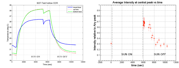
Fig. 4 (Left) SCF-Test of the Hollow CCR. Drop in temperature at the end of heating phase due to quick turn in front of laser to set up subsequent FFDP acquisition. (Right) Intensity variation of FFDP at the central peak during the SCF-Test. Relative error on intensity is ±10%.
Test of a Galileo-IOV prototype retroreflector
In June 2010, INFN proceeded with a series of test requested by ESA on a prototype CCR of the upcoming IOV satellites of the Galileo constellation. The measurements were undertaken to analyze the thermal and optical properties of the CCR, which is an uncoated prism made of Suprasil 311 with a height of 23.3 mm. Its front face is the result of the intersection of a circle of 43 mm diameter with an equilateral triangle with edge length of ~ 114 mm (see Fig. 5). The front face has an inscribed circle of 33 mm diameter. To compensate for the velocity aberration, three Dihedral Angle Offsets (DAO) of 0.8 arcsec are introduced in the angles between the faces. The CCR was then inserted in an Aluminum housing.

Fig. 5 (Left) Galileo-IOV CCR tested at LNF. (Right) Drawing of the CCR.
The CCR was installed inside an aluminum enclosure to replicate the condition of a CCR inside the array, surrounded by other CCR housings. The aluminum housing was suspended from the payload support/positioning system so it could be rotated around the vertical direction. The first test performed on this CCR was the measurement of τCCR, at the temperatures of 310 K and 370 K of the external Al housing. Data taken with the IR camera (front face temperature) were fitted exponentially to extract the information of the characteristic heating time. These data showed a surprisingly short time constant compared with the previous measurements performed on solid cubes of similar volume with back coating. For the aluminum-coated CCRs of GPS/GLONASS/GIOVE satellites the relaxation time was of the order of ~ 1000 sec while for the engineering prototype of LAGEOS, described earlier, the measured τ was thousand of seconds. Moreover τCCR increases from 310K to 370K by ~30% while simulations indicate a decrease 1/T3, in case of a dominant radiative heating exchange between the CCR and its housing cavity. The difference in behavior could be caused by non-perfect isolation of the CCR with its housing during subsequent conductive heating exchange. This test was performed with the solar simulator beam orthogonal to the CCR front face; however it is crucial to test different incidence angles. Depending on the orientation of the CCR with respect to the solar simulator beam, there are cases in which total internal reflection is broken (breakthrough) and rays pass through the CCR, heating the internal surfaces of the housing. For uncoated CCRs this occurs when a light ray is tilted with respect to the symmetry axis above 17°. During its movement in orbit, the CCR experiences different solar inclination angles. For this reason the tests included simulations of Galileo critical orbits whose angular momentum is orthogonal to Sun-Earth direction. For this particular orbit the inclination vector of solar rays lies on a plane, and the orientation with respect to the CCR front face changes from -90° to +90°.
These conditions are reproduced in the laboratory by rotating the LRA inside the chamber at discrete angle steps for the proper orbital period. Galileo satellites have a quasi-circular orbit with a semi-major axis of ~29600 Km, which corresponds to an orbital period of ~14 hrs. The in-chamber simulation extended over half of the orbit period, from the moment in which sun rays rose above CCR front face until they disappeared on the other side, corresponding to a period of ~7 hrs (a schematic view of the test procedure is in Fig 6. left). A detailed description of the test can be found in [3].
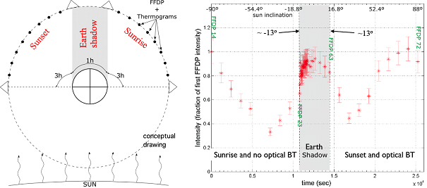
Fig. 6 (Left) Galileo GCO conceptual drawing. (Right) FFDP average intensity, relative to the first FFDP, of the IOV CCR during the GCO at 24 μrad
The retroreflector was positioned inside the chamber with a circular aluminum plate behind it, in order to simulate the presence of the satellite behind the LRA, thereby shielding the rear side of the housing from cold deep space. Heater tape on the back of the aluminum plate controlled its temperature for initial starting conditions for each measurement run. Tests showed degradation in the range of 25% in optical performance over the exposure cycle as compared to as large as 87% with the old GPS/GLONASS/GIOVE ones CCR’s. Averaging over the entire orbit, the CCR average intensity at 24 μrad velocity aberration would have a degradation of ~ 35%. The prototype IOV CCR shows the expected FFDP degradation due to optical breakthrough during sunset; for almost symmetric sun inclinations during sunrise, there is no thermal optical breakthrough. Thermal breakthrough could be due to a CCR mounting scheme with relatively large thermal conductance, as the tests described earlier seemed to point out.
Test of the LLRRA-21/MoonLIGHT retroreflector
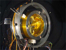
Fig. 7 MoonLIGHT CCR inside the SCF cryostat
Measurement were performed on a 100 mm CCR [4] being studies as a lunar target. The CCR was installed inside the cryostat with its housing attached to the rotation system. FFDP measurements were performed using a laser beam smaller than the CCR front face. In simulated space environment, the CCR was heated with the solar simulator, with the beam orthogonal to the CCR. The irradiation of the Sun was then simulated at lower elevations, so the CCR was rotated from 30 degrees clockwise to 30 degrees counterclockwise with respect to the solar simulator. There was a total internal reflection breakthrough situation only in one direction. Figure 8 shows how the temperature difference from the front face to the tip varies and how the FFDP changes during the different thermal phases. This depicts the expected thermal distortion of the return beam to the Earth as the solar aspect and exposure changes.
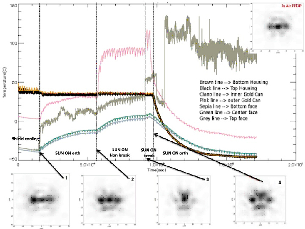
Fig. 8 Temperature variations of the housing parts and relative FFDP
Retroreflector Array Analysis and Modeling
Publications related to retroreflector array analysis and modeling (correction of velocity aberration, types of arrays, e.g., coated vs. uncoated, solid vs. hollow, diffraction far field patterns, effective cross section, etc.) are available.
References
[1] S. Dell'Agnello, et al., Creation of the new industry-standard space test of laser retroreflectors for the GNSS and LAGEOS, Adv. in Space Res. 47, 822-842.
[2] A. Boni, et al., World first SCF-Test of the NASA-GSFC LAGEOS Sector and Hollow Retroreflector, 17th International Laser Ranging Workshop, Bad Koetzing (Germany), 2011.
[3] S. Dell’Agnello et al., ETRUSCO-2: an ASI-INFN Project of Technological Development and SCF-Test of GNSS Retroreflector Arrays, 3rd Int. Colloquium- Galileo Science, Copenhagen, Sept 2011.
[4] S. Dell’Agnello, et al., Isothermal FFDP-Test and SCF-Test of Flight-quality Uncoated Cube Corner Laser Retroreflectors, 17th International Laser Ranging Workshop, Bad Koetzing (Germany), 2011.
[5] [4] D. Currie, S. Dell’Agnello, G. Delle Monache (2011). A Lunar Laser Ranging Retroreflector Array for the 21st Century. Acta Astron. 68, 667–680.
Related Publications
- Degnan, John. "A Tutorial on Retroreflectors and Arrays for SLR", Presentation and paper from ILRS Technical Laser Workshop "Satellite, Lunar and Planetary Laser Ranging: Characterizing the Space Segment", INFN-LNF, Frascati, Italy, November 05-09, 2012
- Additional publications